At Labs we spend a decent amount of effort analysing the security of embedded systems and Internet of Things (IoT) devices. A significant portion of our time is spent figuring out how to instrument devices in order to gain a granular view of how the hardware is reacting to our queries. Instrumentation may take place at a high level such as running a test program within the embedded operating system that is already resident in the device memory, at a low level such as a specifically crafted and loaded test program running directly on the microprocessor, or at some level between those two extremes.
This post will cover how we tackle the low level instrumentation of a BeagleBone Black device from enabling JTAG access to loading a test program onto the device. Having an emulator to connect to a JTAG port is the best case scenario, giving you as the tester the ability to upload new firmware, breakpoint, step, and inspect registers.
Required Materials
Preparing the board for JTAG access
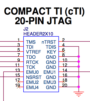
The first task in working with the Beaglebone is to solder on a connector to the board giving us easy access to the JTAG port. Thankfully the BeagleBone Black PCB does nothing to hide its JTAG port and access can be obtained simply by soldering on a compact TI (cTI) 20-pin male header onto the JTAG breakout pins. On the bottom of the BBB you will find P2, this is the JTAG breakout port.
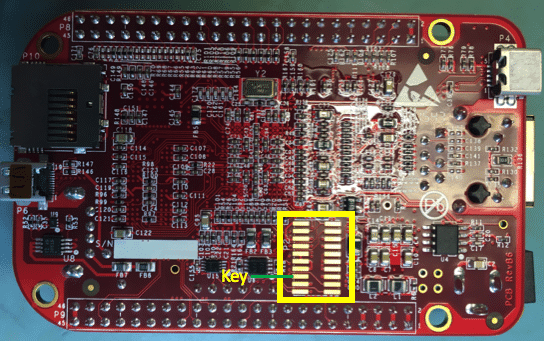
Solder the keyed 20 pin header to P2. If you have a non-keyed 20 pin header, remove pin 6 (the key) from the part in order to make your own keyed header. When you are done soldering, triple check that you have no bridges between the pins.

JTAG Emulator
Not all boards are as easy as the Beaglebone Black to get up and running with JTAG. After getting the connector installed, the next step is to hook up the port to your emulator. Be sure that if you are purchasing a new JTAG emulator just for this project that you order one that is compatible with the cTI 20-pin JTAG connector. If you want to utilize something like aFlyswatter you are going to need a 20 Pin Adapter or create your own monstrosity of an adapter.
For fun, we hooked up the JTAGulator in order to verify our pinouts. The pins look like this:
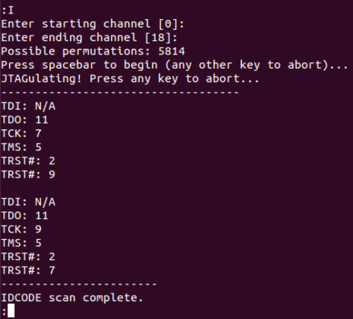
If I were a little more organized I would have plugged the JTAGulator channels 1 for 1 to the header pin numbers. After mapping the channel numbers, we get this:
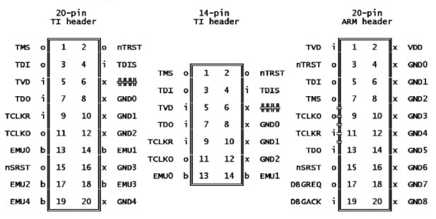
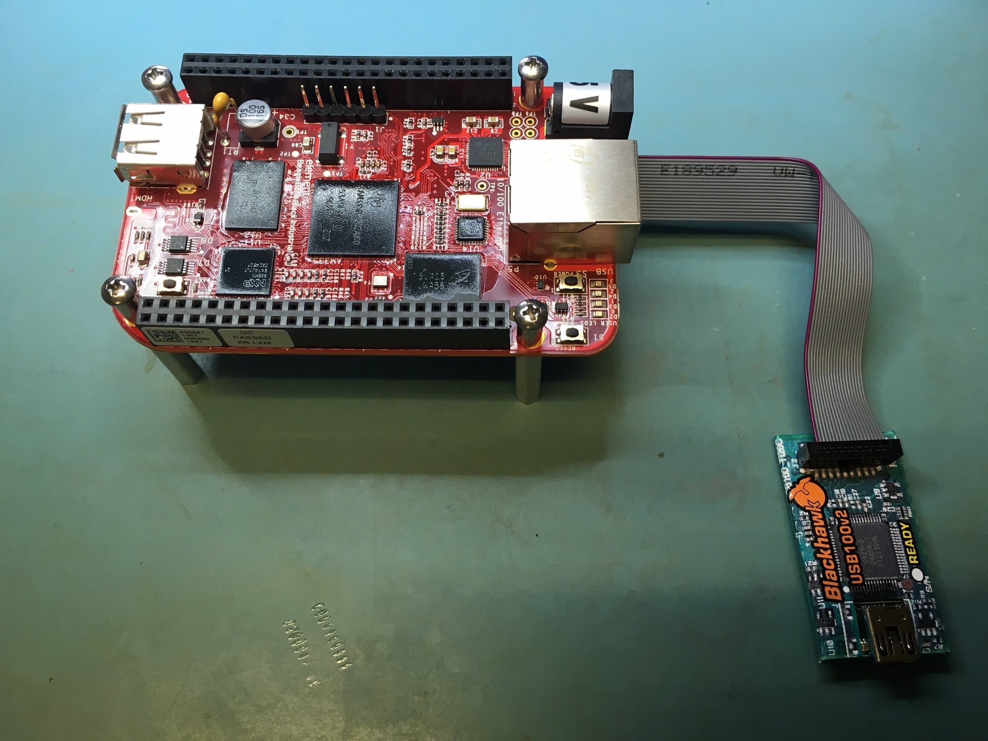
If you want to take the easy way out, go purchase a XDS100V2 or USB100v2 or TMDSEMU100v2U-20T. There is not much to say here other than go ahead and plug in the ribbon cable to the connector that you previously soldered on being mindful of the key. Whatever you purchase, make sure it works with a Texas Instruments AM3358 Sitara Processor. The AM335x microprocessors, based on the ARM Cortex-A8 processor, are enhanced with image, graphics processing, peripherals and industrial interface options such as EtherCAT and PROFIBUS. Here are the common JTAG header layouts:
Code Composer Studio (CCS)
There are a couple different paths at this point. You could go connect your flyswatter, download OpenOCD, and be on your way. I am going to choose to use my TMDSEMU100v2U and install CCS to talk to that emulator. We will get into more advanced examples later on, but for now, lets start with the standard ‘hello world’ application.
Download and Install CCS
There is nothing out of the norm for getting CCS running. It is basically Eclipse under the hood. Go ahead download the application, extract the download contents, and run the installer. Be sure to read the README in order to ensure you have all of the dependenices. It is a graphical installer, so if you are in Linux and the bin file just keeps on returning after you invoke it, check the library dependenices.
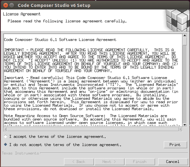
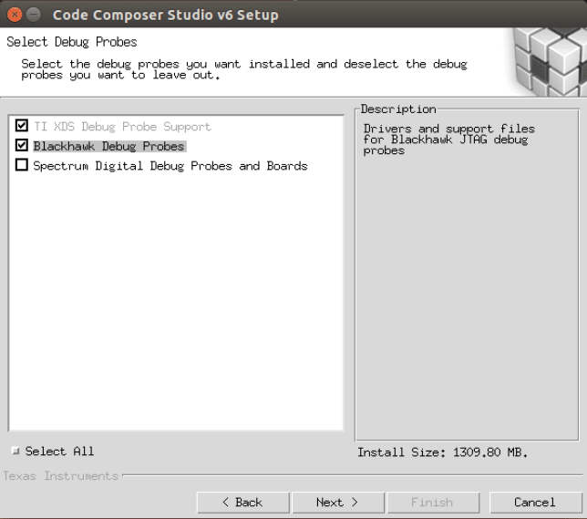
As you are blindly clicking through the install configurations, make sure you select the packages for the emulator that you are planning to use.
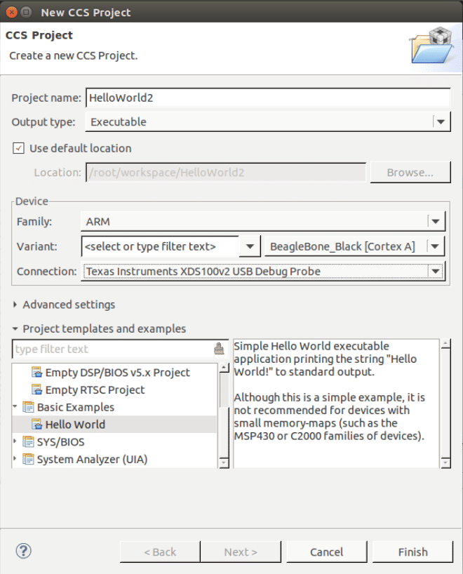
Create new CCS Project
If you have used Eclipse before, the following steps should look pretty familiar. Start by creating a new CCS Project and selecting the ‘helloworld’ as the base project. From there, choose the Beaglebone as your device and the USB100v2 (assuming that is what you are using) as your emulator. This will pop up the standard “helloworld” skeleton.
Go ahead and build that test application. This is a dump of my build output for your reference:
**** Build of configuration Debug for project HelloWorld2 ****

/opt/ti/ccsv5/utils/bin/gmake -k all
Building file: ../hello.c
Invoking: ARM Compiler
"/opt/ti/ccsv5/tools/compiler/arm_5.1.14/bin/armcl" -mv7A8 --code_state=32 --abi=eabi -me --include_path="/opt/ti/ccsv5/tools/compiler/arm_5.1.14/include" -g --define=am3359 --diag_warning=225 --display_error_number --diag_wrap=off --preproc_with_compile --preproc_dependency="hello.pp"  "../hello.c"
Finished building: ../hello.c

Building target: HelloWorld2.out
Invoking: ARM Linker
"/opt/ti/ccsv5/tools/compiler/arm_5.1.14/bin/armcl" -mv7A8 --code_state=32 --abi=eabi -me -g --define=am3359 --diag_warning=225 --display_error_number --diag_wrap=off -z -m"HelloWorld2.map" --heap_size=0x800 --stack_size=0x800 -i"/opt/ti/ccsv5/tools/compiler/arm_5.1.14/lib" -i"/opt/ti/ccsv5/tools/compiler/arm_5.1.14/include" --reread_libs --warn_sections --display_error_number --diag_wrap=off --xml_link_info="HelloWorld2_linkInfo.xml" --rom_model -o "HelloWorld2.out"  "./hello.obj" "../AM3359.cmd" -l"libc.a"
<Linking>
Finished building target: HelloWorld2.out
Boot the board
Ensure that you have the following wires connected
- USB cable to JTAG Emulator
- Ribbon cable from JTAG Emulator to BBB
- 5v USB (or barrel plug) to BBB
Before you plug the power adapter to the BBB you will need to depress the “Boot Switch” on the beaglebone, then supply the power to the BBB. The BeagleBoneBlack comes with SPL, u-boot and the Linux kernel already burned into its eMMC. Because eMMC is the default boot method on the BBB whenever you provide power it will boot into Linux. We want to prevent this so as to ensure that the board is stuck in the Boot ROM. This has the bonus effect of keeping the device in a ‘pure’ state. To do this hold down the S2 button when applying power. You can let it go after a second or so. If you are connected to the serial pins you can see the serial output spitting out ‘C’ characters. This is the ROM telling us that it is waiting for a valid SPL image from an SD card. If you see any of the User LEDs (opposite the RJ45 connector from the power plug) lit up blue this means that Linux has booted.
Start the debug session
With your BBB powered, and the JTAG emulator connected, go ahead and kick off the debug process. Here is my console dump from kicking off the process on my setup:
CortxA8: Output: ****  AM335x BeagleBlack Initialization is in progress ..........
CortxA8: Output: ****  AM335x ALL PLL Config for OPP == OPP100 is in progress .........
CortxA8: Output: Input Clock Read from SYSBOOT[15:14]:  24MHz
CortxA8: Output: ****  Going to Bypass...
CortxA8: Output: ****  Bypassed, changing values...
CortxA8: Output: ****  Locking ARM PLL
CortxA8: Output: ****  Core Bypassed
CortxA8: Output: ****  Now locking Core...
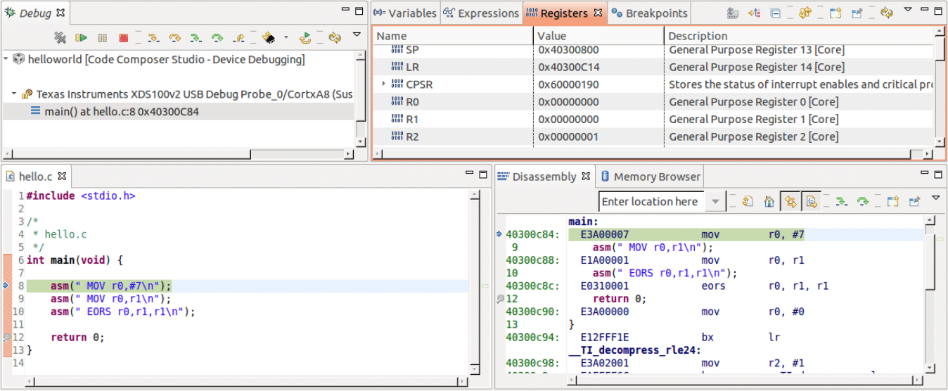
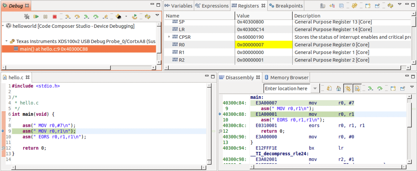
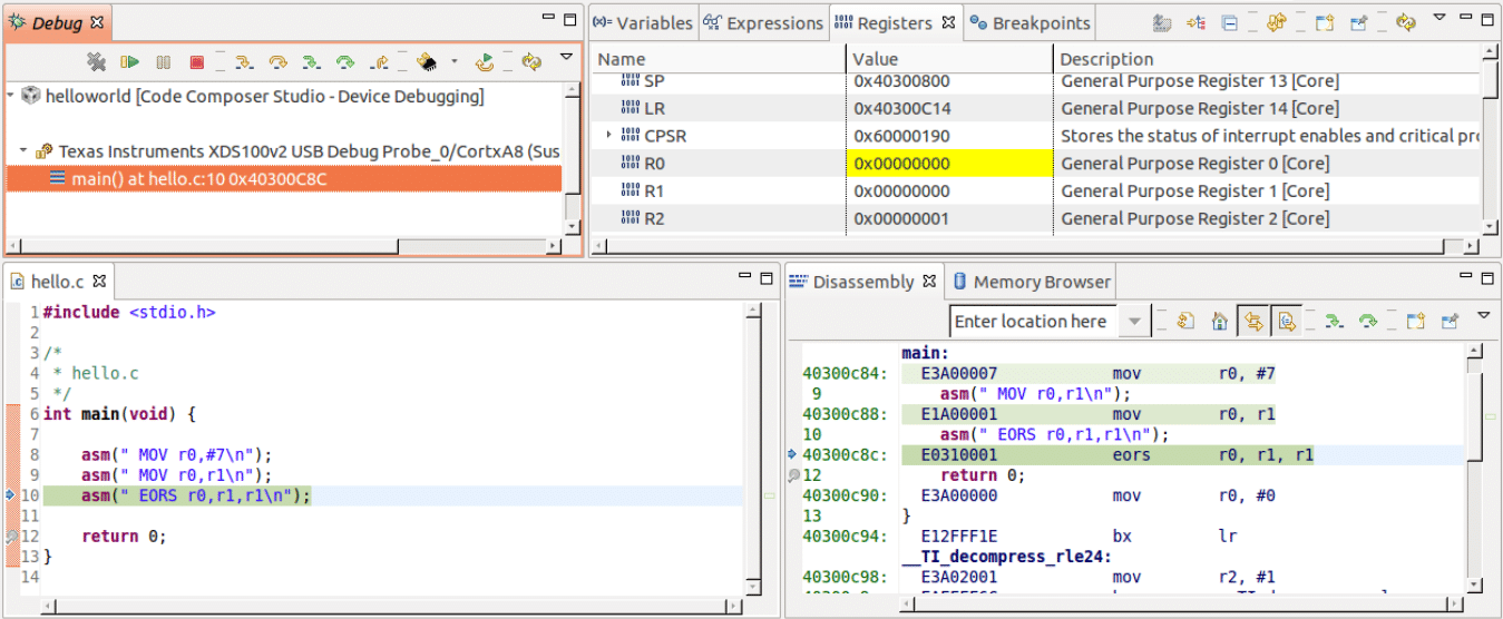
At this point the BBB has been loaded with your ‘helloworld’ firmware. You can step through this just like your other software based debug sessions.
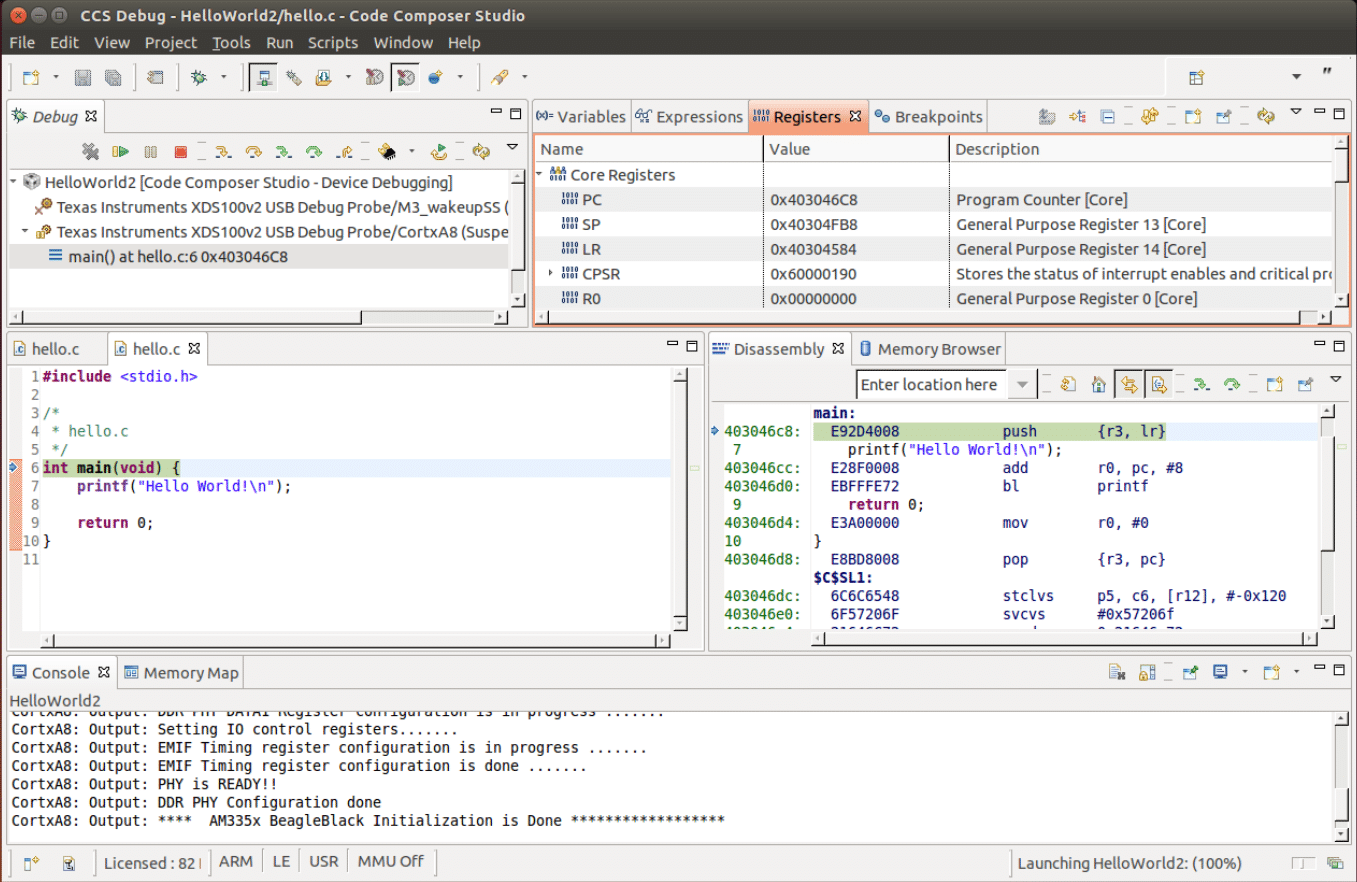
At this point, play around with the environment. Perhaps throw some assembly into the helloworld.c file to see how to work with the debug session. In the set of images below there are some basic ARM assembly shifting some register values around.