Requirements
- Pixhawk loaded with the latest
px4fmu-v2bootloader and firmware release. We are using Release v1.4.4. - IDA Pro
- JTAG/SWD Adapter (Optional)
- Capstone
- Keystone
Preparation
The Pixhawk comes preloaded with a bootloader and firmware image, if so desired, we can pull the latest PX4 firmware release. The firmware on our board is the nuttx-px4fmu-v2-default.px4 file in the zip archive and we were able to upload this to the hardware with the px_uploader.py script from the GitHub repository.
PX4 Firmware Extraction, Uploading
The pre-compiled PX4 Firmware releases are in JSON file format and have a .px4 file extension. Prototypes for these files are located at PX4/Firmware/Images. Example prototype:
{
    "board_id": 9,
    "magic": "PX4FWv1",
    "description": "Firmware for the PX4FMUv2 board",
    "image": "",
    "build_time": 0,
    "summary": "PX4FMUv2",
    "version": "0.1",
    "image_size": 0,
    "git_identity": "",
    "board_revision": 0
}
The "image" field contains the binary application image after being max compressed with zlib and base64 encoded. The "image_size" field is also checked to confirm it matches the size of the "image" field. We will only need to update these two fields to upload a custom image to the board. We can use the script below (px_parser.py) to extract or update the binary image for a given .px4 file:
#px_parser.py
import json
import argparse
import zlib
import base64

# ARG PARSER
parser = argparse.ArgumentParser()
mx = parser.add_mutually_exclusive_group(required = True)
parser.add_argument('file', type = argparse.FileType('r'))
mx.add_argument('-e', '--extract', action = 'store_true')
mx.add_argument('-c', '--compress', action = 'store_true')
parser.add_argument('-r', '--reference', type = argparse.FileType('r'))
args = parser.parse_args()

if args.compress:
    if args.reference is None:
        parser.error("--compress requires --reference: px4 reference file")


# EXTRACT IMAGE, BASE64 DECODE, ZLIB DECOMPRESS
if args.extract:
    px4_data = json.load(args.file)
    px4_image_compressed = base64.b64decode(px4_data['image'])
    px4_image = zlib.decompress(px4_image_compressed)

    # WRITE OUT IMAGE
    with open('px4_image.bin', 'wb') as f:
        f.write(px4_image)
        f.close()

# ZLIB MAX COMPRESS, BASE64 ENCODE, INSERT INTO JSON, UPDATE IMAGE_SIZE
if args.compress:
    px4_data = json.load(args.reference)
    px4_image = args.file.read()
    px4_image_compressed = zlib.compress(px4_image,9)
    px4_image_compressed_64encoded = base64.b64encode(px4_image_compressed)
    px4_data['image'] = px4_image_compressed_64encoded
    px4_data['image_size'] = len(px4_image)

    with open(args.reference.name, 'w') as f:
        json.dump(px4_data, f)
Extraction
Extract the firmware by downloading the latest release (nuttx-px4-v2-default.px4), and then executing python px_parser -e nuttx-px4-v2-default.px4
Uploading
On macOS, running: python px_uploader.py nuttx-px4fmu-v2-default.px4 --port=/dev/cu.usbmodem1 will get the image onto the PixHawk. Conversely, you could also use QGroundControl for this task by following their guide.
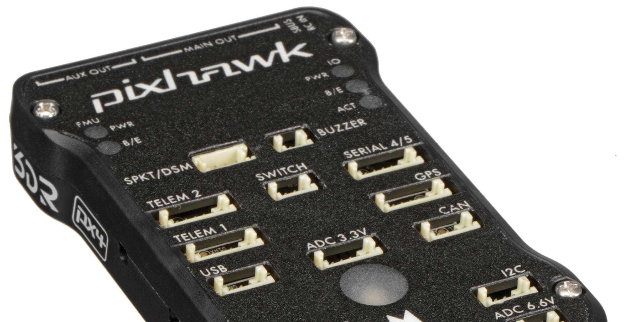
Firmware Modification
After the default firmware has been uploaded, we can power on the board and visually identify when the board transitions from the bootloader to the firmware application. The FMU B/E (Bootloader/Error) LED flashes repeatedly when running the bootloader, and stops when the board starts running the firmware application. Since we have not performed any wiring setup, the application will end up blinking the main LED red to signal an error.
Here is a clip of the board booting up:
Our goal is to inject code that blinks an LED at the very start of the firmware application, directly after the bootloader finishes. After the injected code runs, execution should go back into the original control flow and resume normal activity. In doing this, we should be able to visually see if the injection was successful. As you can imagine, this technique could be used just like a printf(“helloworld”) in software debugging when we start inspecting points of interest in the firmware. Board interfaces like the FMU B/E LED is a good choice for this purpose since it is normally supposed to be off during the transition into the application. Another good option on this board is the BUZZER where as instead of lighting an LED we could play a beep or tune.
The processor that we are working with is the 32-bit STM32F427 with a Cortex M4 Core that runs the THUMB instruction set. Some basic assembly knowledge is needed to accomplish the goal. In our example, we mainly use MOV and BL instructions to setup arguments and perform function calls. The FMU B/E LED corresponds with the GPIO E12 pin. It is important to be familiar with the GPIO toggling process which involves enabling the GPIO peripheral’s clock, setting the pin to output mode, and then toggling the pin.
Image Base and Entry Point
The image base address and entry point for the application are important values to identify. The board will load the firmware application at the base address. We want to replicate this as well since it is much easier to work with the program as it would be represented in memory. The entry point is also necessary as that is where the bootloader ends and the application begins, this is the area in which we will perform our LED toggling. Given that we have access to source, both of these values can be found in the source code located in PX4/Bootloader.
hw_config.h : The application is loaded at the base address of 0x08004000
101 /****************************************************************************
102  * TARGET_HW_PX4_FMU_V2
103  ****************************************************************************/
104
105 #elif  defined(TARGET_HW_PX4_FMU_V2)
106
107 # define APP_LOAD_ADDRESS               0x08004000
bl.c : The second word of the image is our entry point. This is 0x080a4e10 in our case.
 243 void
244 jump_to_app()
245 {
246 	const uint32_t *app_base = (const uint32_t *)APP_LOAD_ADDRESS;
247
248 	/*
249 	 * We refuse to program the first word of the app until the upload is marked
250 	 * complete by the host.  So if it's not 0xffffffff, we should try booting it.
251	 */
252	if (app_base[0] == 0xffffffff) {
253		return;
254	}
255
256	/*
257	 * The second word of the app is the entrypoint; it must point within the
258	 * flash area (or we have a bad flash).
259	 */
260	if (app_base[1] < APP_LOAD_ADDRESS) {
261		return;
262	}
263
264	if (app_base[1] >= (APP_LOAD_ADDRESS + board_info.fw_size)) {
265		return;
266	}
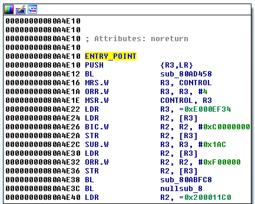
Here is a view of the disassembly at the entry point for the default firmware image:
Bootloader
The bootloader for our board (px4fmuv2_bl.elf) can provide some useful information. Since the bootloader is blinking the FMU B/E LED when running, it must already have some functions or code that allow it to do this. In fact the bootloader is using libopencm3 to perform these tasks. Of course another approach is to write custom assembly to achieve the goal, but given that someone has already written the code we need, we might as well reuse.
Let’s open up the bootloader source code and identify the regions that perform GPIO setup and toggling. main_f4.c is the place to look. Some of the constants can be looked up in hw_config.h to get the libopencm3 names.
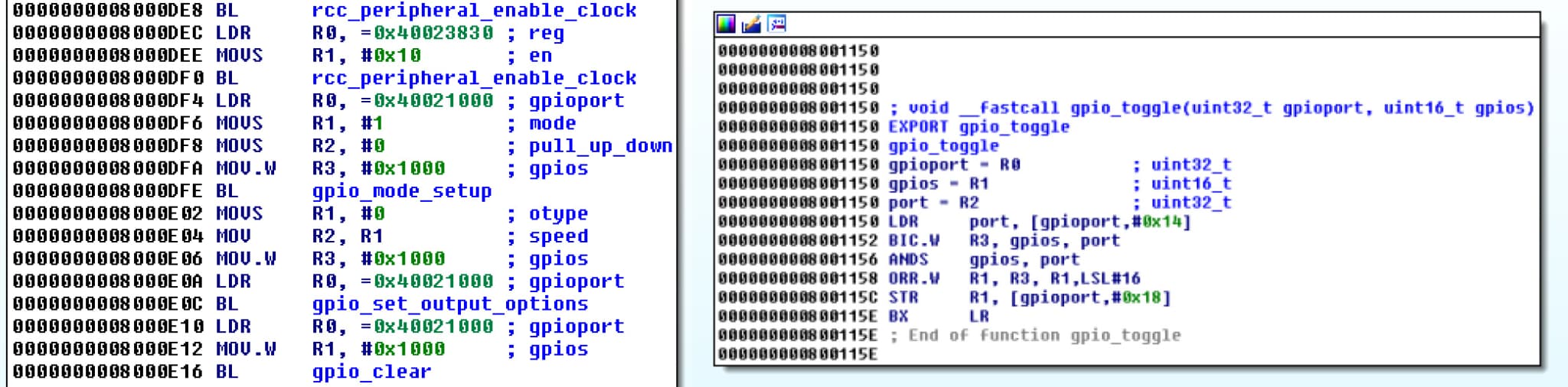
main_f4.c:
 379 /* initialise LEDs */
380 rcc_peripheral_enable_clock(&RCC_AHB1ENR, BOARD_CLOCK_LEDS);
381 gpio_mode_setup(
382	BOARD_PORT_LEDS,
383	GPIO_MODE_OUTPUT,
384	GPIO_PUPD_NONE,
385	BOARD_PIN_LED_BOOTLOADER | BOARD_PIN_LED_ACTIVITY);
386 gpio_set_output_options(
387	BOARD_PORT_LEDS,
388	GPIO_OTYPE_PP,
389	GPIO_OSPEED_2MHZ,
390	BOARD_PIN_LED_BOOTLOADER | BOARD_PIN_LED_ACTIVITY);
391 BOARD_LED_ON(
392	BOARD_PORT_LEDS,
393	BOARD_PIN_LED_BOOTLOADER | BOARD_PIN_LED_ACTIVITY);
394
Thanks to debugging symbols, we can go and open the bootloader binary up in IDA and locate the corresponding assembly. It is then just a matter of recording down the function addresses and constant values. Below is an image of the disassembly for the LED initialization functions as well as the gpio_toggle function.
Patching Helper
It is very useful to use a tool that helps with the patching. We decided to use Capstone and Keystone to do perform the disassembly and assembly that is necessary.
Below is a python module that was written to provide helping functionality for patching. As previously mentioned, it is much easier to work on the binary image using virtual addresses. When the image is read in, the binary is abstracted so that it appears to have been loaded at the base address in memory. The image read and write functions also provide the necessary address translation. There is also a function to extend the image with null bytes to create space for code we will inject. Another solution is to find an existing location to overwrite.
Finally there is the patching function which takes in a string of assembly instructions and a location to target. The instructions are encoded individually by using Keystone. We need to consider the possibility that an existing instruction might be partially or fully overwritten. So the approach is for Capstone to read the target location beforehand, and identify overwritten bytes as partial or full instructions. If an instruction has been partially overwritten, we need to finish overwriting it with NOPS in order to prevent issues when we resume normal program execution. The overwritten instructions are stored to be used later in repairing the execution flow.
#PIMG.PY
from capstone import *
from keystone import *
class Segment(object):
  def __init__(self,name,vaddr,offset,size):
    self.name = name
    self.vaddr = vaddr
    self.offset = offset
    self.size = size
class Image(object):
    def __init__(self,filepath,base):
            self.fp = filepath
            self.contents = self.readImage(self.fp)
            self.base = base
            self.size = len(self.contents)
            self.segments = []
            self.entrypoint = None
            self.end = self.base + self.size
    def readImage(self, filepath):
            try:
                    with open(filepath, 'rb') as f:
                            data = f.read()
                            f.close()
                            return data
            except:
                    raise IOError
    def createSegment(self, s_name, s_vaddr, s_offset, s_size):
            s = Segment(s_name, s_vaddr, s_offset, s_size)
            self.segments.append(s)
            return
    def read_image_vaddr_range(self, start, end):
            if start > end:
                    return
            for segment in self.segments:
                    if ((start&end) >= segment.vaddr and
                            (start&end) <= segment.vaddr + segment.size):
                            start = start - segment.vaddr + segment.offset
                            end = end - segment.vaddr + segment.offset
            return self.contents[start:end]
    def write_image_vaddr_range(self, start, byte_list):
            for segment in self.segments:
                    if start >= segment.vaddr and start <= segment.vaddr + segment.size:
                            start = start - segment.vaddr + segment.offset
            b = bytearray()
            b.extend(self.contents)
            for i,byte in enumerate(byte_list):
                    b[start+i] = byte
            self.contents = str(b)
            return
    def extendZero(self,num_bytes):
            original_end = self.end
            self.segments[-1].size += num_bytes
            self.size += num_bytes
            self.end += num_bytes
            b = bytearray()
            b.extend(self.contents)
            for i in range(num_bytes):
                    b.append(0x00)
            self.contents = str(b)
            return original_end
    def patch(self, code, start):
            ks = Ks(KS_ARCH_ARM, KS_MODE_THUMB + KS_MODE_LITTLE_ENDIAN)
            cs = Cs(CS_ARCH_ARM, CS_MODE_THUMB + CS_MODE_MCLASS + CS_MODE_LITTLE_ENDIAN)
            cs.skipdata=True
            # encode each insn
            encoding = []
            code = filter(None,code.split(';'))
            current = start
            for insn in code:
                try:
                    result = ks.asm(insn,addr=current)[0]
                except KsError:
                    print "ERROR",insn
                encoding += result
                current += len(result)
            size = len(encoding)
            # decode to determine overwritten bytes
            overwritten = []
            padding = 0
            for insn in cs.disasm(self.read_image_vaddr_range(start,start+size), start):
                if insn.id == 0:
                    insn = cs.disasm(self.read_image_vaddr_range(insn.address,insn.address + insn.size + 2), insn.address).next()
                    padding += 2
                overwritten.append(insn)
            # add nops
            nops = [0,191] * (padding/2)
            encoding += nops
            # write to image
            self.write_image_vaddr_range(start,encoding)
            #return
            end = start + size
            return overwritten, end, size, padding
    def write_image_to_disk(self):
            with open(self.fp + '.modified', 'wb') as f:
                f.write(self.contents)
                f.close()
            return
Patching
The steps we need to take to perform the hook:
- Extend the firmware to obtain space for our custom code
- Inject custom functions used by our main function and identify the entry point for the hook
- Select an existing instruction in the firmware to overwrite with our hook that calls into our entry point
- Inject the main function which performs:
- Toggle LED
- Restore original state and execute overwritten code
- Return to where we hooked from
In the example code, the image is extended by 1024 bytes (sufficient for our uses). Two functions are injected: A software NOP delay and a LED toggle function that uses the NOP delay. It is easier to inject the hook into a location where it will not overwrite any relative instructions. The main function will setup the GPIO E LED, call the LED toggle function, and then clean up. In our case the GPIO peripheral clock for the LED pin has already been enabled at the hooking location. It ends up the only setup needed is to set GPIO_E12 to output mode. It is important to properly clean up and revert to normal execution without damaging the expected state of the program. This requires us to save and restore any registers we touched, and execute the original instructions that we had overwritten. The final step is to write all changes to disk and then upload to the board via px_uploader.py.
After producing the patched image, you can open it up in IDA to review the modifications. The ARM Little-endian processor should be selected. The ROM starting address and loading address should also be set to our image base of 0x08004000.
Here is the full patching code which uses the library posted above:
#PPATCH.PY
from capstone import *
from keystone import *
# our helper module
from pimg import *
# function addresses & constants
rcc_peripheral_enable_clock = 0x080013c8
ahb1enr = 0x40023830
ahb1enr_iopeen = 0x10
gpio_mode_setup = 0x08001160
gpio_set_output_options = 0x0800119a
gpio_toggle = 0x08001150
gpio_set = 0x08001140
gpio_clear = 0x08001144
gpio_E = 0x40021000
gpio_12 = 0x1000
def mov_32(address):
mov_w = '0x%x'%(address & 0xFFFF)
mov_t = '0x%x'%(address >> 16)
return (mov_w,mov_t)
def reg_mov_32(register,address):
return "MOVW {0},#{1};MOVT {0},#{2};".format(register,*mov_32(address))
def call(address):
return "BL 0x%X;"%address
# open firmware image and set base
image = Image("px4_image.bin",0x08004000)
# create segment
image.createSegment("ROM",image.base,0,image.size)
# set the entrypoint
image.entrypoint = 0x080a4e10
# extending our firmware image to allocate space for injected code
target = image.extendZero(1024)
###
# FUNCS
###
# We inject two functions that we will call later
# NOP DELAY FUNCTION
nop_delay = target
NOP_DELAY_CODE = "SUBS R10,#1;"
+ "BNE 0x%X;"%nop_delay
+ "BX LR;"
_,target,_,_ = image.patch(NOP_DELAY_CODE,nop_delay)
# LED_TOGGLE_N function W/DELAY
led_toggle_n = target
nop_count = 0x1ebc200
LED_TOGGLE_N_CODE = "PUSH {LR};"
+ reg_mov_32('R0',gpio_E)
+ "MOV R1, #0x%X;"%gpio_12
+ call(gpio_toggle)
+ reg_mov_32('R10',nop_count)
+ call(nop_delay)
+ "SUBS R9,#1;"
+ "BNE 0x%X;"%(led_toggle_n+0x2)
+ "POP {LR};"
+ "BX LR;"
_,target,_,_ = image.patch(LED_TOGGLE_N_CODE,led_toggle_n)
###
# HOOK
###
# inject at 0x080a4e24 looks good, not overwriting a relative instruction
ENTRY_JUMP_LOCATION = image.entrypoint+0x14
# Injecting our call instruction at 0x080a4e24
ENTRY_JUMP_CODE = call(target)
ow,_,_,_ = image.patch(ENTRY_JUMP_CODE, ENTRY_JUMP_LOCATION)
# save the overwritten instructions for future use
OVERWRITTEN = ""
for ins in ow:
OVERWRITTEN +="{0} {1};".format(ins.mnemonic,ins.op_str)
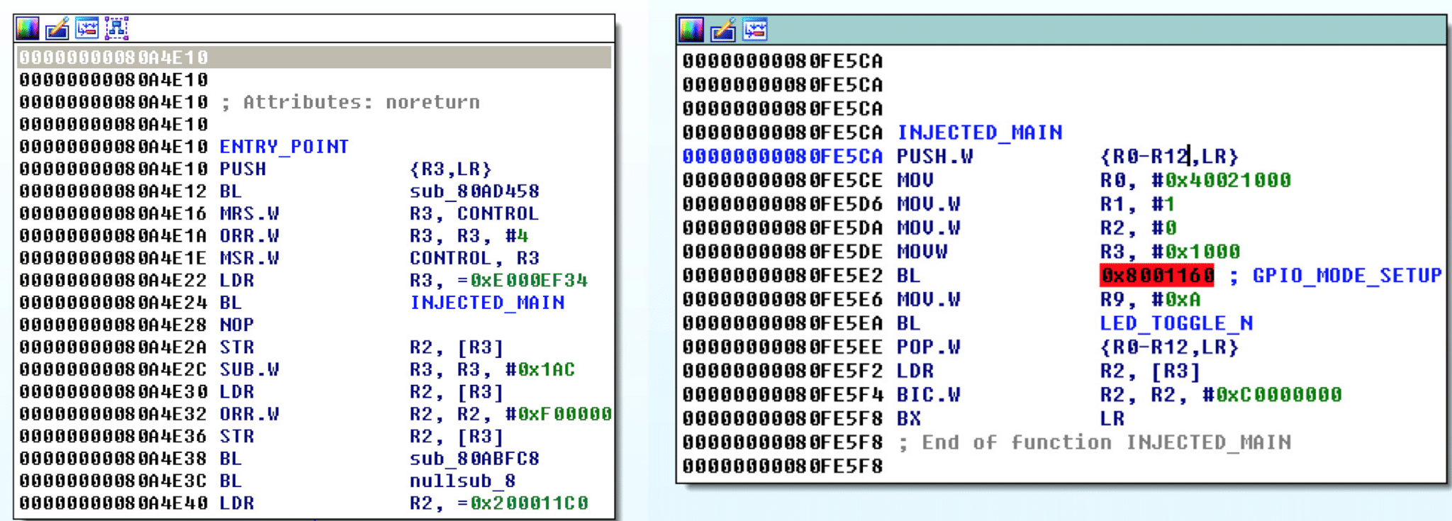
###
# MAIN
###
PROLOGUE = "PUSH {R0-R12,LR};"
EPILOGUE = "POP {R0-R12,LR};"
RETURN = "BX LR;"
MODE_SETUP = reg_mov_32('R0',gpio_E)
+ "MOV R1,#1;"
+ "MOV R2,#0;"
+ "MOVW R3,#0x%X;"%gpio_12
+ call(gpio_mode_setup)
'''
OUTPUT_OPTIONS = reg_mov_32('R0',gpio_E)
+ "MOV R1,#0;"
+ "MOV R2,R1;"
+ "MOVW R3, #0x%X;"%gpio_12
+ call(gpio_set_output_options)
'''
TOGGLE = "MOV R9, #0x%X;"%10
+ call(led_toggle_n)
MAIN_CODE = PROLOGUE + MODE_SETUP + TOGGLE + EPILOGUE + OVERWRITTEN + RETURN
_,_,_,_ = image.patch(MAIN_CODE,target)
###
# DONE
###
# write to disk
image.write_image_to_disk()
Results
We should have a successfully patched image at this stage. You can view the changes to the firmware image and board behavior below.